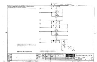
Resistor Board G626
Order Number: XX-XXXXX-XX
This document is a technical schematic for a Resistor Board (G626) produced by Digital Equipment Corporation in 1967. The circuit diagram details a series of connections involving resistors (R1–R8), capacitors (C1–C4), and diodes (D1–D3) linked to various input points (T, S, R, N, L, K, J, V) and power terminals (F and D). It also includes a 1/2 amp fuse (F1) and specifies component standards, such as 10-watt, 1% low-inductance resistors and D671 diodes. The document notes that a complete parts list can be found under A-PL-G626-0-0.
Site structure and layout ©2025 Majenko Technologies