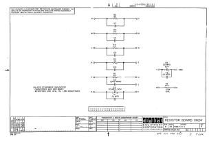
Resistor Board G624
Order Number: XX-XXXXX-XX
This document is an engineering schematic for the Digital Equipment Corporation Resistor Board G624 (Revision D). The circuit design consists of multiple parallel resistor-capacitor pairs connected between various inputs and outputs (labeled M through T, and H through U), along with supplementary capacitors (C1, C8, C9) and a biasing resistor (R6). The schematic includes standard component specifications, noting that unless otherwise indicated, capacitors are 680 MMFD and resistors are 10W, 1% tolerance, low-inductance components.
Site structure and layout ©2025 Majenko Technologies