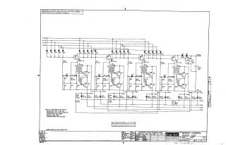
Memory Common Driver G212
Order Number: XX-XXXXX-XX
This document is a technical schematic for the Digital Equipment Corporation "Memory Common Driver G212," dated 1966. It illustrates the circuit design for a driver module, detailing the configuration of transistors (DEC 2894-3A and T-2050), transformers, diodes (D664), resistors, and capacitors. The schematic includes various input/output pins (labeled A through K, M, N, P, S, etc.) and specifies that all resistors are 1/4W 5% (with specific exceptions), capacitors are in MMFD, and the board uses a specific etch pattern. A transistor and diode conversion chart is included to cross-reference DEC components with industry-standard parts.
Site structure and layout ©2025 Majenko Technologies