Tapped Delay Line B311
Order Number: XX-XXXXX-XX
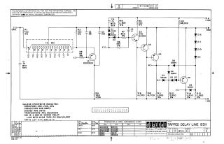
Summary: This document is a technical schematic diagram for a Tapped Delay Line circuit, manufactured by Digital Equipment Corporation (1966).
Key features of the schematic include:
- Circuit Components: The circuit utilizes a DEC 16-05529 delay line, five transistors (DEC 2904, 3009B, and three others), and multiple diodes (D664 and D662).
- Specifications: It includes a "Transistor & Diode Conversion Chart" mapping the internal DEC part numbers to industry-standard EIA numbers (e.g., DEC 3009B corresponds to 2N3009).
- Technical Notes: The diagram specifies that unless otherwise indicated, resistors are 1/4W 10%, capacitors are in MMFD, and diodes are D662. It also notes the assembly is built with 25NS taps.
- Power Requirements: The circuit is designed for use with a 10V and -15V power supply.
Site structure and layout ©2025 Majenko Technologies