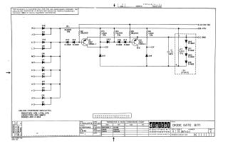
Diode Gate B171
Order Number: XX-XXXXX-XX
This document is an electrical schematic for a Digital Equipment Corporation "Diode Gate" circuit (model B171), dated June 1964. The circuit utilizes two DEC 2894-1 transistors (Q1 and Q2) and a network of D-662 diodes to perform logic operations. It features a multi-input array (labeled H through V) connected through diode gates, with biasing resistors (R1-R6) and a capacitor (C1) for signal stabilization. The schematic also specifies that all unspecified resistors are 1/4W with 10% tolerance, capacitors are in MFD, and standard diodes are D-664.
Site structure and layout ©2025 Majenko Technologies