Adder Gate B167
Order Number: XX-XXXXX-XX
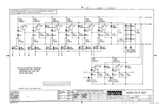
Summary: This document is a technical schematic for a Digital Equipment Corporation "Adder Gate B167," dated November 1966. The circuit diagram details the configuration of transistors (2N4258), diodes (D664, D662, 1N645, 1N3606), and resistors used in the gate's logic design. The schematic includes voltage inputs for +10V, ground (GND), and -15V, along with various labeled signal terminals (N, S, F, M, P, T, H, R, V, J, U, E, K, L, O, D). A conversion chart for the components and a parts list reference (A-PL-B167-0-0) are also included.
Site structure and layout ©2025 Majenko Technologies