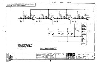
Diode Gate B113
Order Number: XX-XXXXX-XX
This document is a technical schematic for a Diode Gate circuit (part number B113-0-1) produced by Digital Equipment Corporation in 1964. The diagram illustrates a series of three-input logic gates utilizing DEC2894-1B transistors and D-662/D-664 diodes. Key components include multiple 12,000 and 68,000-ohm resistors, 1,500-ohm resistors for the lower section, and various capacitors. The schematic provides the circuit logic layout, including input nodes (D, E, J, K, N, O, P, U) and output nodes (F, L, R, V).
Site structure and layout ©2025 Majenko Technologies