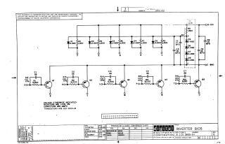
Inverter B105
Order Number: XX-XXXXX-XX
This document is a technical schematic for the Digital Equipment Corporation Inverter B105 circuit. It illustrates a five-channel transistor-diode converter array. Each channel consists of a transistor (Q1 through Q5) with a base-input network comprising a capacitor (56 MMFD) in parallel with a 100-ohm resistor, and a 3,000-ohm resistor leading to the input terminals. The collectors of these transistors are connected to a common voltage rail regulated by a network of diodes (D6-D9) and capacitors (C5, C6, C8, C9), outputting to a -15V supply and ground. The schematic includes specifications for component values, indicating that all resistors are 1/4W 5% tolerance and capacitors are measured in MMFD.
Site structure and layout ©2025 Majenko Technologies