Analog Amplifiers A214
Order Number: XX-XXXXX-XX
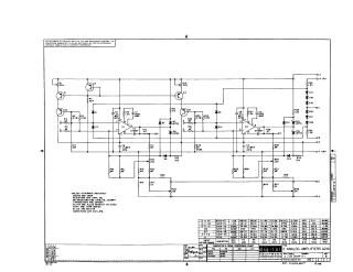
Summary: This document is a technical schematic for the "Analog Amplifiers A214" circuit, manufactured by Digital Equipment Corporation in 1969. The circuit utilizes two MC1709 operational amplifiers (E1 and E2) alongside 2N4250 transistors, D664 diodes, and various resistors and capacitors to perform signal conversion. The schematic includes a table detailing specific component value variations (R3, R4, R7, R21, R24, R25, R26, R29, R31, R32, and R42) required to achieve different input voltage ranges, ranging from ±1 to 0–+10. The circuit is designed to operate with a +5V power supply and provides multiple outputs labeled C, D, E, U, and V.
Site structure and layout ©2025 Majenko Technologies