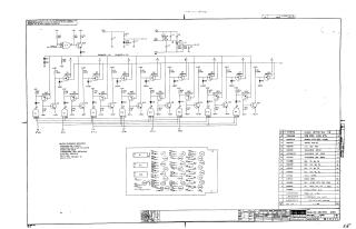
Analog Switch A133
Order Number: XX-XXXXX-XX
This document is a technical schematic for an A133 Analog Switch module. It details the circuit design, which utilizes a series of DEC5534D transistors and 2N5163 transistors configured in a switching array. The diagram includes logic gates (E1, E2, E3), resistors, diodes, and capacitors, along with input control lines (labeled 2^0 through 2^3). Additionally, the document provides a comprehensive parts list, specifying components such as transistors, resistors, diodes, and integrated circuits, along with their respective Digital Equipment Corporation part numbers and quantities required for assembly.
Site structure and layout ©2025 Majenko Technologies