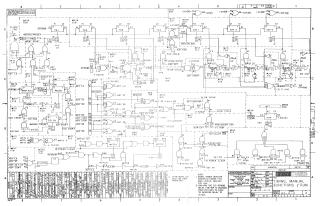
Timing, Manual Functions and Run
Order Number: XX-XXXXX-XX
This document contains a comprehensive set of logic circuit diagrams and technical specifications for the Digital Equipment Corporation (DEC) PDP-8/I computer. It serves as a detailed engineering reference for the machine's internal operations.
The document covers the following key areas of the PDP-8/I architecture:
- Logic and Timing: Detailed schematics illustrating the timing chains, run control logic, and instruction registration processes that govern the computer's operational cycles.
- Registers and Gating: Logic diagrams for major internal registers (such as AC, MB, MA, and PC) and the gating circuitry required for data movement and manipulation.
- Memory Control: Schematics for memory management, including memory timing, sense amplifiers, inhibit drivers, and X/Y axis selection logic for core memory access.
- I/O Interfaces: Logic for peripherals and system communication, specifically detailing the Teletype transmitter and receiver interfaces, as well as I/O level converters.
- System Indicators: A diagram of the console switches and indicator lights used for machine operation and status monitoring.
- Module Utilization: Two reference sheets at the end of the document provide a mapping of which electronic modules (e.g., M-series boards) are utilized in various locations within the computer's backplane.
The schematics use standard logic symbols, with notes specifying that "signal names indicate asserted states for high (H) levels per DEC STD 054." The drawings include revision histories, engineering component numbers, and cross-references to other system drawings.
Site structure and layout ©2025 Majenko Technologies