Module Utilization
Order Number: XX-XXXXX-XX
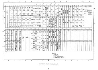
Summary: This document provides a comprehensive map of module utilization for a PDP-8 computer system. It consists of two sheets that detail the physical slot assignments for various components, including memory, control panels, interface drivers, parity units, and bus connections.
- Sheet 1 (D-MU-8L-0-18): Focuses on the layout of registers, memory bus interfaces, parity controls, and input/output drivers (such as sense and inhibit drivers). It also lists optional configurations at the bottom, including data break, memory parity, power fail, high-speed reader/punch, and a note regarding GB10 compatibility.
- Sheet 2 (D-MU-8L-0-18): Details the utilization for control panel functions, interrupt handling, timing and clock circuitry, I/O device controllers (such as teletype and reader/punch), and memory stack connections.
The diagrams organize these components into a grid format (columns 1–44), indicating the specific module placement required for the system's architecture.
Site structure and layout ©2025 Majenko Technologies