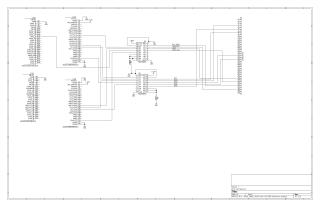
Dectape Interface
Order Number: XX-27E28-F4
This schematic, titled "Dectape Interface," illustrates a circuit designed to connect a BeagleBone Black single-board computer to a 40-pin connector (P1, labeled CONN_01X40), likely for interfacing with a Dectape drive.
The design utilizes four BeagleBone Black expansion headers (P8/A, P8/B, P9/A, P9/B) to access a wide range of digital and analog I/O. Key components include two 74LVC245 octal bus transceivers (U2 and U3). These transceivers provide buffering and level shifting between the BeagleBone Black and the external 40-pin connector. U2 handles signals such as ALLHALT, FWDREV, UNIT, and STOP_GO, while U3 manages signals like RTT, RD0, RD2, RD1, and RMT. The interface incorporates various BeagleBone Black I/O lines, including General Purpose Input/Output (GPIOs 0, 1, 2, 3), Timers, UARTs (1-5), I2C (1-2), SPI (1), PWM (EHRPWM1A, EHRPWM2A, EHRPWM2B), and Analog Inputs (AIN0-AIN6). Power supply connections (+3.3V, +5V, and GND) are also integrated.
Site structure and layout ©2025 Majenko Technologies